Second Prototype (SMD version)
TracNav
- Home
Hardware
- Reverse Engineering
- Encoders (code)
Manufacturing
Development
- First prototype
- Second prototype (SMD version)
- Emulating MID
- HW1.0-beta1 (third revision)
- HW2.0 (4th revision)
CarPC
Software
Stuff
User projects
Prepare
Finally I spend around one month (only my free time) to prepare a layout design with EAGLE for my second prototype. This time it is all based on SMD components and should be pretty small. The problem now is to find a good company which could etch the board for me. I finally stopped at PCB-Pool.de which did the work really good. I had to order there a 1dm2 board, so that I got second kit for free. For the etching process, I payed around 50.- Euros. For all the components used on the board, I payed again around 80.- Euros. However I had to order the components of the board in big packages. I've received all of them from RS-Online.de. If I compute the final material price for one such kit, then we will end up in around 60-70.- Euros, just for the material, which is still ok for a prototype.
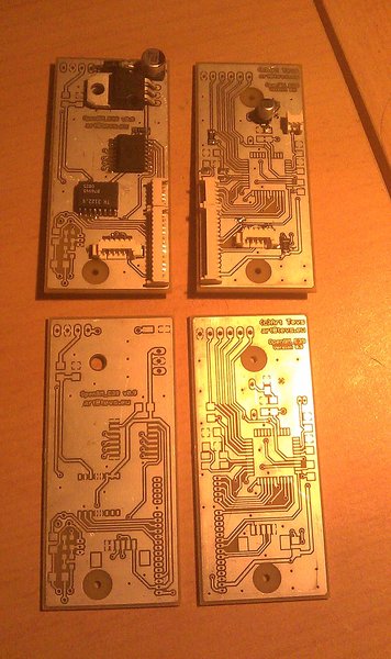
The final 2nd prototype layout is looking like this:
The connectors on the right board are used for the programmer device. Later they will be used to drive external Relais or FETs. They can be use dfor example to switch audio sources for the original BMW Radio coming from CarPC or DVD/DVB-T. The connectors on the left board are the main car connector: DimmLight? (background light pwm signal), GND, IBus Signal and +12V current.
Build
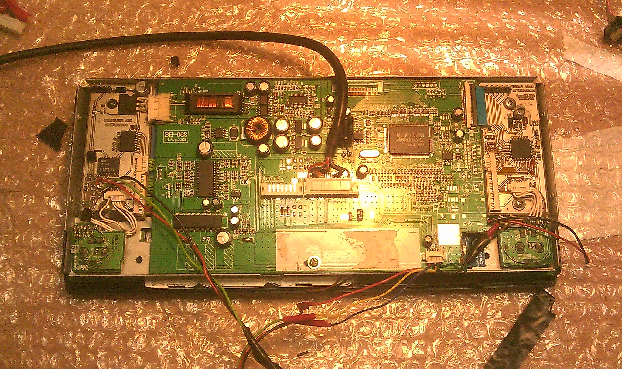
Finally after one week the PCBs arrived and I was surprised about the quality. Unfortunately my camera was not available at this time, hence I had to make pictures with my cell-phone :( After several weekends of soldering (have I told already that I am working only on weekends on this project), I build the prototype into the housing. Now I am using 14MHz crystal to drive the ATmega. Additionally I am using PCF8574 port expanders to ask for button and rotary encoders state. This helps me also to reduce wirings and to make everything more suitable for this small housing.
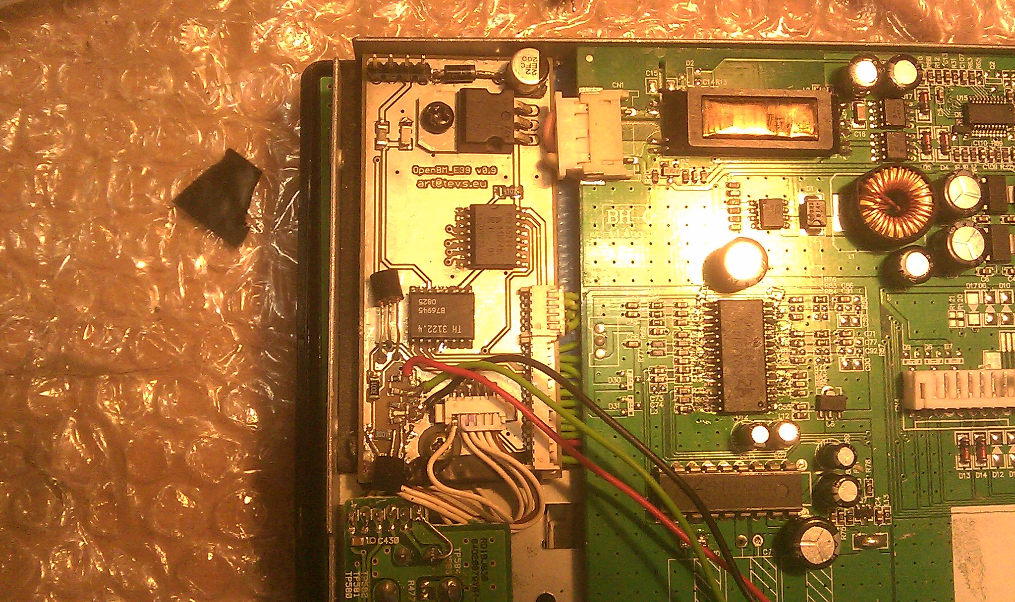
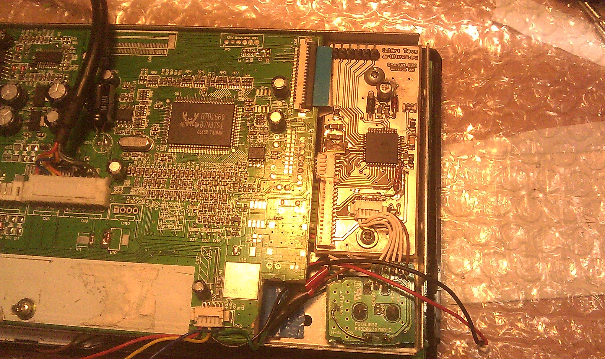
Of course, this is a prototype, so not everything went pretty well. I had to patch the board design slightly to meet real-world requirements. This is a close up view (sorry for bad quality) of my hardware patches:
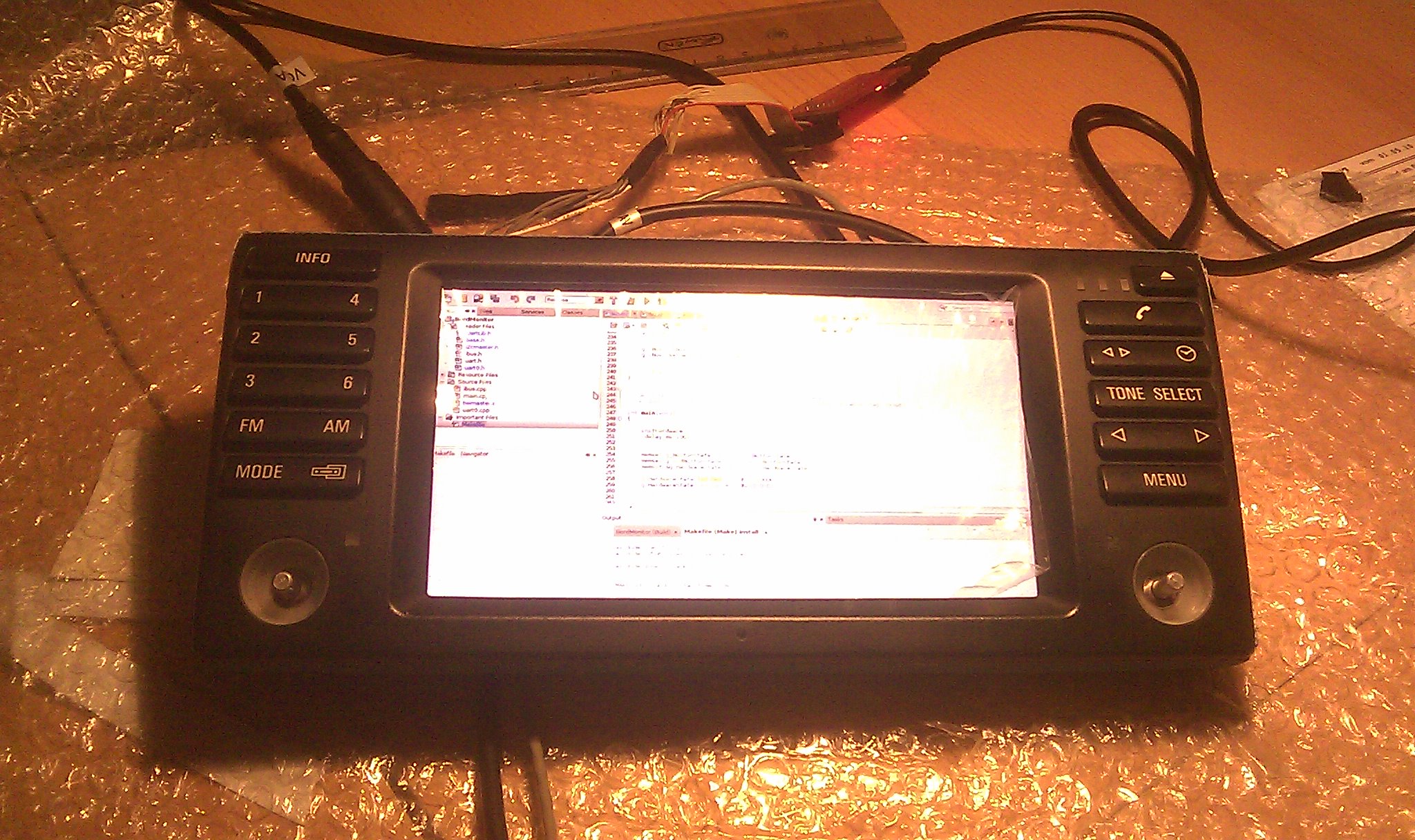
VGA input from my laptop for testing purpose:
![(please configure the [header_logo] section in trac.ini)](../../../../www.tevs.eu/media/images/projects/openbm_logo.png)

