Reverse Engineering
TracNav
- Home
Hardware
- Reverse Engineering
- Encoders (code)
Manufacturing
Development
- First prototype
- Second prototype (SMD version)
- Emulating MID
- HW1.0-beta1 (third revision)
- HW2.0 (4th revision)
CarPC
Software
Stuff
User projects
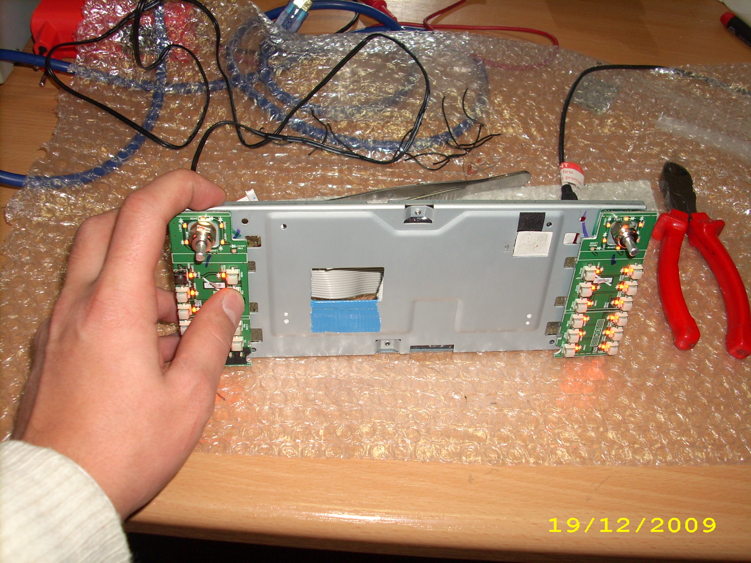
So our OpenBM device should be able to work inside of the original 16:9 bord monitor housing. For this we would like to know how all the buttons work there. Here is an image showing those both original pcb on which the buttons and LEDs are installed (klick on image for full size).
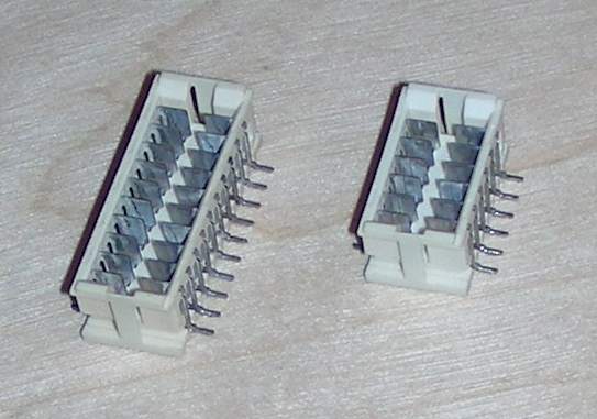
The connection to the main board is done through one 12pin and one 20pin connector. The connector is some kind of special ALPINA connector, at least I wasn't able to find such one anywhere. So, we will need them in order to connect our board with the button board. Here is an image, how this buttons do looks like (this image is taken from Bengt-Olof Swing, who works on a similar project, see here.)
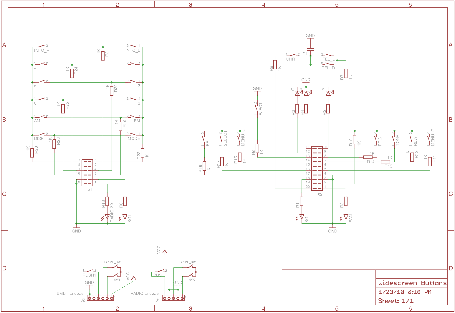
After spending several hours the main schematics of those button boards has been decoded. Here is an image, I've created with EAGLE, showing how those both PCB works. All the status LEDs resistors are 80Ohm, so I assume they were driven originally with around 3,3V. The background LEDs seems to be driven with 12V pwm modulated signal, however not sure for now. On the E39-forum.de somebody found out the manufacturer of compatible rotating knobs for the 4:3 monitor. I think for the 16:9 it could be the same. The original knobs where a special development for Alpina. The compatible one is that one: Grayhill 61C22-01-04-02, data sheet. Please visit the Encoder page for more information about used encoders.
Note: The both encoders showed on the image, do not show the original connecting, but the way, how I changed it in order to easy access them with an uC. So recheck this first, if you like to build same thing!!!
![(please configure the [header_logo] section in trac.ini)](http://www.tevs.eu/media/images/projects/openbm_logo.png)


